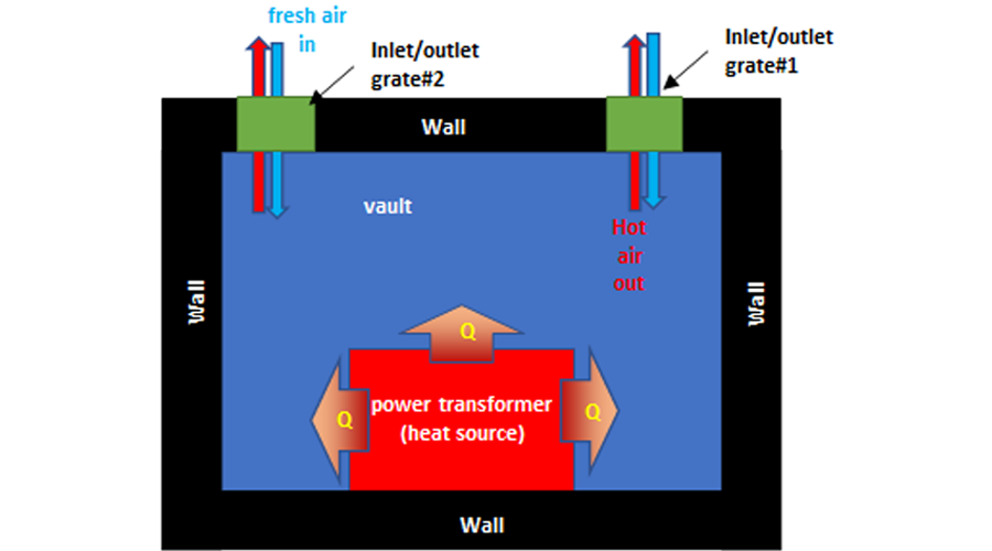
Scenero 1: Traditional Transformer Vault Design with open grates.
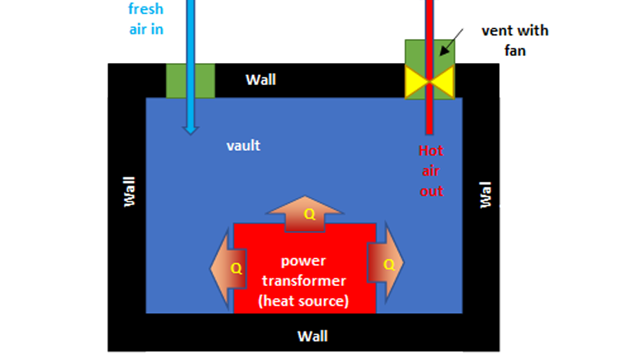
Scenario 2: Transformer Vault with forced Ventilation, no grates.
Both scenarios model using Computational Fluid Dynamics (CFD)
CFD simulation of a 500kVA power transformer installed in a standard 11.5ft L x 4.5ft W x 6.5ft H vault
Scenario 1 – Vault construction with dual grating
Scenario 2 – Vault construction using 2000CFM VaultVent for forced cooling and vault vent intake
Scenario 1 – Transformer Vault Simulation w metal grates
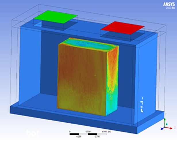
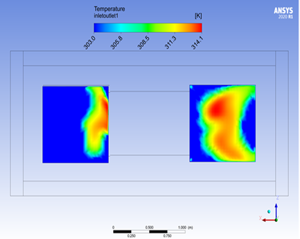
Scenario 1 – Fresh air enters (blue) and hot
air exits (red) provides poor heat transfer
since warm and cooler air flow through same grate with maximum flow rate of 0.15 Kg/s

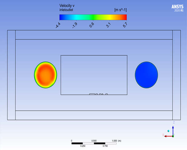
Scenario 2 –
Vault construction using 2000CFM VaultVent for forced cooling and vault vent intake
